

How to Successfully Design a Power Module?
2025-05-27 10:28:32 1271
Power modules are power supplies that can be mounted directly onto a printed circuit board (see Figure 1) and feature power supplies for application-specific integrated circuits (ASICs), digital signal processors (DSPs), microprocessors, memories, field-programmable gate arrays (FPGAs), and other digital or analog loads. Generally, these modules are referred to as point-of-load (POL) power supply systems or point-of-use power supply systems (PUPS). Because of the many advantages of modular construction, a wide variety of modules are used in systems for high-performance telecommunications, networking, and data communications. While there are many advantages to using modules, engineers designing power supply modules and even most on-board DC/DC converters often overlook reliability and measurement issues. In this article, we will discuss these issues in depth and propose solutions for each.
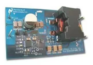
Figure. 1 Power supply
Advantages of using power supply modules
Currently different suppliers in the market to introduce a variety of different power supply modules, and different products have different input voltage, output power, functionality and topology. The use of power modules saves development time and allows products to be introduced to the market faster, thus making power modules superior to integrated solutions. Power modules have several other advantages:
● Each module can be individually and rigorously tested to ensure a high level of reliability, including a power-on test to weed out substandard products. Integrated solutions are more difficult to test because the entire power supply system is tied to other functional systems on the circuit.
Different suppliers can design modules of the same size according to existing technical standards, providing engineers designing power supplies with a wide range of options.
● Each module is designed and tested according to standard performance regulations, helping to minimize the risks associated with adopting new technologies.
An integrated solution requires the replacement of the entire motherboard in the event of a power supply system problem, while a modular design saves cost and development time by simply replacing the problematic module.
Easily overlooked power module design issues
Although the modular design has the above advantages, the modular design and the on-board DC/DC converter design also have their own problems, which many people do not know enough or do not pay enough attention to. The following are some of these problems:
● Measurement of output noise; ● Design of magnetic systems; ● Breakdown of synchronous buck converters; ● Reliability of printed circuit boards.
Each of these issues is discussed below, along with a variety of simple techniques that can be used to solve them.
Output Noise Measurement Techniques
All power supplies that use switching mode will output noise. The higher the switching frequency, the more important it is to use the correct measurement techniques to ensure that the measurements are accurate and reliable. When measuring output noise and other important data, the Tektronix probe shown in Figure 2 (commonly referred to as a cold-nozzle probe) can be used to ensure that the measurements are accurate, reliable, and predictable. This measurement technique also ensures that ground loops are minimized.
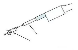
Figure. 2 Measured output noise figure
When making measurements we also need to take into account the fact that the measuring instrument may have propagation delays. Most current probes have a greater propagation delay than voltage probes. Measurements where both voltage and current waveforms must be displayed at the same time cannot be guaranteed to be accurate unless the different delays are equalized manually.
Current probes also feed inductance into the circuit. Typical current probes input 600nH of inductance. For high-frequency circuit designs, the inductance fed through the probe can affect the accuracy of di/dt current measurements and can cause large errors in the measurement figures, since the circuit cannot handle more than 1mH of inductance. If the inductor is saturated, another more accurate method of measuring current can be used, for example, we can measure the voltage of a small tap resistor in series with the inductor.
Design of Magnetics
The reliability of the magnetic core is another issue that is often overlooked. Most output inductors use powdered iron cores because powdered iron is the lowest cost material. Powdered iron cores are composed of approximately 95% pure iron particles, which are bonded together using an organic adhesive. The adhesive also separates each iron particle so that there are air spaces inside and outside the core.
Iron powder is the raw material that makes up the core, but iron powder contains small amounts of impurities such as manganese and chromium, which can affect the reliability of the core depending on the amount of impurities contained. The relative distribution of these impurities can be determined by taking a close look at a cross-section of the core using a spectral electron microscope (SEM). The reliability of a core depends on the predictability of the material and the reliability of its supply.
If powdered iron cores are exposed to high temperatures for a long period of time, core losses may increase, and once the losses increase, they can never be recovered because of increased eddy current losses due to molecular decomposition of the organic bonding agent. This phenomenon is known as thermal aging and may eventually lead to thermal runaway of the core.
The magnitude of core loss is affected by a number of different factors such as AC flux density, operating frequency, core size and material type. In high-frequency operation, for example, most of the losses are eddy current losses. In low-frequency operation, hysteresis loss is the largest loss.
Eddy-current losses cause the core to heat up, which affects the efficiency. Eddy-current loss occurs when a ferromagnetic material is subjected to different magnetic fluxes at different times of the day, resulting in a continuous flow of electric current in the object. Eddy current loss can be reduced by using a thin sheet of ferromagnetic material instead of a solid ferromagnetic material as the core. An example of such a core is Metglas, which is wound with magnetic tape. Other suppliers of ferromagnetic products, such as Magnetics, also produce tape-wound cores.
Core suppliers, such as Micrometals, provide engineers designing magnetic products with up-to-date information and calculations on heat aging of cores. Powdered iron cores with inorganic binders are not subject to heat aging. These cores are commercially available, including Micrometals' 200C series of cores.
Synchronous Buck Converter Breakdown
Synchronous buck converters are widely used in power supply systems such as point-of-load power supplies (POL) or point-of-use power supplies (PUPS) (Figure 3). These synchronous buck converters replace the clamping diodes of conventional buck converters with high and low side MOSFETs in order to reduce the loss of load current.
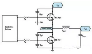
Figure. 3 Synchronous Buck Converter
Engineers designing buck converters often overlook the problem of “shoot-through”. Breakdown” occurs when both the high and low side MOSFETs are fully or partially activated at the same time, allowing the input voltage to carry current directly to ground.
Breakdown causes a spike in current at the moment of switching and prevents the converter from operating at peak efficiency. We should not use a current probe to measure the breakdown, as the inductance of the probe can seriously interfere with the operation of the circuit. Instead, we can check the gate/source voltages of the two field effect transistors (FETs) for spikes. This is another way to detect breakdown. (The gate/source voltages of the upper MOSFETs can be monitored in a differential manner.)
The following methods can be used to minimize the occurrence of breakdown.
The use of a controller chip with a “fixed dead time” is one of the possible methods. This controller chip ensures that after the upper MOSFET is turned off, there is a delay before the lower MOSFET is restarted. This is a simple approach, but it should be implemented with care. If the dead time is too short, it may not prevent breakdown. If the deadtime is too long, the conduction loss increases because the diode built into the underlying field effect transistor is activated for the entire deadtime. Since this diode conducts during the dead time, the efficiency of the system using this method depends on the characteristics of the diode built into the underlying MOSFET.
Another way to reduce breakdown is to use a controller chip with “adaptive dead time”. The advantage of this approach is that the gate/source voltages of the upper MOSFET can be constantly monitored to determine when to start the lower MOSFET.
When the upper MOSFET starts, an inductive sense causes a dv/dt spike at the gate of the lower MOSFET, which pushes up the gate voltage (Figure 4). If the gate/source voltage is high enough to start it, breakdown occurs.
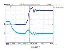
Figure. 4 Amplitude of dv/dt sense level in low-side MOSFETs.
The adaptive deadtime controller is responsible for monitoring the gate voltage of the MOSFET externally. As a result, any newly added external gate resistor will divert some of the voltage from the controller's built-in pull-down resistor, such that the gate voltage will actually be higher than what the controller is monitoring.
Predictive gate driving is another viable option by using digital feedback circuitry to detect the conductance of the built-in diode and adjust the dead-time delay to minimize the conductance of the built-in diode and ensure that the system can perform at maximum efficiency. With this approach, more pins would need to be added to the controller chip, increasing the cost of the chip and the power module.
It should be noted that even with a predictive gate drive, there is no guarantee that the field effect transistor will not start due to inductive sensing of the dv/dt.
Delaying the startup of the high-end MOSFETs also helps to minimize breakdowns. While this approach can reduce or eliminate breakdowns, the disadvantages are higher switching losses and reduced efficiency. Choosing a better MOSFET can also help reduce the amplitude of the dv/dt inductance voltage at the bottom MOSFET gate; the higher the ratio of Cgs to Cgd, the lower the inductance voltage at the MOSFET gate.
The test case for breakdown is often overlooked, such as during load transients - especially whenever the load is lifted or suddenly reduced - when the controller is constantly generating narrow-frequency pulses. Most of today's high-current systems are multiphase designs that utilize driver chips to drive the MOSFETs, but the use of driver chips complicates the breakdown problem, especially when the load is in the middle of a transient. For example, interference from narrow-frequency drive pulses, coupled with propagation delays in the driver, can lead to breakdown.
Most driver chip manufacturers specify that the pulse width of the controller must not fall below a certain minimum requirement, below which no pulse will be fed into the gate of the MOSFET.
Additionally, manufacturers have added a programmable dead time (TRT) feature to their driver chips to enhance the accuracy of the adaptive conversion timing. This is accomplished by placing a dead-time setting resistor between the TRT pin and ground to determine the dead time during the high and low side conversions. This deadtime setting function, coupled with a propagation delay, shuts down the complementary MOSFETs during conversion to avoid a breakdown condition in the synchronous buck converter.
Reliability
Any module must be rigorously tested at an early stage to ensure that the design is sound and reliable, so that unexpected problems do not occur at the final stage of the production process. The module must be able to be tested in the customer's system to ensure that all relevant factors that could lead to system failure, such as fan failure, intermittent fan stalling, etc., are taken into account. Engineers using decentralized architectures expect to design systems that will last for many years with little or no failure. Since test figures show that the MTBF of power supply modules is several million hours, it is not difficult to achieve this goal.
But what is often overlooked is the reliability of the printed circuit board. According to the current trend, the area of the printed circuit board is shrinking smaller and smaller, but need to handle more and more current, so the increase in current density may lead to hidden or other through-hole can not perform the normal function.
Some of the hidden vias on printed circuit boards must carry large amounts of current, and for these hidden vias, they must be protected by adequate copper guards around them to ensure a more reliable and durable design. The guards also dampen the thermal expansion of the z-axis, otherwise the hidden vias would be exposed if the ambient temperature of the printed circuit board were to change during the manufacturing process or while the product was in use. Engineers must thoroughly review the design of the printed circuit board with the professional advice of the printed circuit board manufacturer, who can provide expert advice on the reliability of the printed circuit board design based on their production capabilities.
Summary
If we are to build a reliable power supply system using power modules, we must address the issue of design reliability. Several major issues were discussed in the above collection, including the reliability of powdered iron cores, the characteristics of magnetic systems, breakdown in synchronous buck converters, and the reliability of printed circuit boards for high-current systems.


