

Constant current source application and multiple circuit design details
2024-11-25 15:53:50 1456
A constant current source is a power supply that can provide a constant current to a load, so constant current sources have a wide range of applications and are essential in many cases. For example, when charging a battery with the usual charger, the charging current will be reduced accordingly as the battery terminal voltage gradually increases. In order to ensure constant-current charging, the output voltage of the charger must be increased at any time, but the use of constant-current source charging can not have to adjust its output voltage, thus reducing labor intensity, productivity has been improved. Constant current source is also widely used in measurement circuits, such as resistor resistance measurement and grading, cable resistance measurement, etc., and the more stable the current, the more accurate the measurement.
Linear constant current source with integrated op-amps
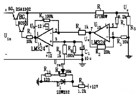
Figure. 1
The use of integrated op-amps constitute a linear constant-current source circuit composition as shown in the figure, two op-amps (a 324) constitute a comparative amplification link, BG1, BG2 transistor constitutes the adjustment link, RL for the load resistor, RS for the sampling resistor, RW for the circuit to provide a reference voltage. Principle of operation: If the power supply fluctuations so that Uin reduced, so that the load current is reduced, the sampling voltage US is bound to reduce the difference between the sampling voltage and the reference voltage (US - Uref) is bound to decrease. Since the UIA is an inverting amplifier, its output voltage Ub = (R5/R4) × Ua is bound to rise, so that through the adjustment link to make the US rise back to the original stable value, to ensure the stability of the voltage of the US, so that the current is stable. When Uin rises, the principle is the same as before, the circuit through the closed-loop feedback system to make US fall to the original stable value, thus making the current constant. Adjustment of RW, then change Uref, can make the current value between 0 ~ 4A continuously adjustable.
Switching constant current source using switching power supply
The switching constant current source circuit of the switching power supply is shown in Fig. 2.3.2. BG1 is the switching tube, BG2 is the driver tube, RL is the load resistor, RS is the sampling resistor, SG35 24 is the pulse-width modulation controller, L1, E2, E3, E4 are the energy storage components, and RW provides the reference voltage Uref. Losses and switching losses of the switching device is the key to improving the efficiency of the circuit. For this reason, the devices chosen are switching transistors and Schottky diodes with low saturation voltage drop and good frequency characteristics.

Figure. 2
An additional coil is wound on the core of choke L1 to reduce the saturation voltage drop of the switching transistor using electromagnetic feedback, and a reasonable structural design is adopted so that the distribution parameters of the circuit can be effectively controlled. When the supply voltage is reduced or the load resistance RL is reduced, the voltage on the sampling resistor RS will also be reduced, then the duty cycle of the square wave output from the 12 and 13 pins of the SG3524 is increased, thus making the BG1 on-time longer, and bringing the voltage U0 back to the original stable value. after the BG1 is turned off, the energy storage elements L1, E2, E3 and E4 ensure that the voltage on the load remains unchanged. When the input supply voltage increases or load resistance value increases caused by U0 increase, the principle is the same as before, the circuit through the closed-loop feedback system to make U0 down to the original stable value, so as to achieve the purpose of stabilizing the load current IL.
Switching constant current source composed of integrated regulator
Switching constant current source using integrated voltage regulator circuit composition as shown in Figure. MC7805 for the three-terminal fixed integrated voltage regulator, RL for the load resistance, RW for the adjustable resistor. Principle of operation: fixed integrated regulator working in the suspended state, between the output terminal 2 and the public terminal 3 access to a potentiometer RW, thus forming a fixed constant current source. Adjusting RW can change the size of the current, the output current is: IL = (Uout/RW) +Iq where Iq is the quiescent current of the MC7805, less than 10m A. When RW is small, i.e., the output current is large, you can ignore the Iq. When the load resistor RL varies, the MC7805 changes its own differential voltage to maintain the current through the load unchanged.
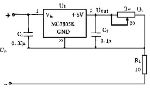
Figure. 3
Determination of RW: The value of RW can be determined from RW=Uout/IL. Since Uout=5 V, IL=0.5~2A, the range of values determined is 2.5~10Ω. Determination of output voltage and load variation range: According to the design requirements, the output voltage of this example is U0=10 V. Since the output current of the constant current source can be adjusted in the range of 0.5~2A, the corresponding range of the load variation is 5-20Ω. The above types of constant current sources have a simple structure and are of high reliability, easy to adjust and have been used in scientific research. Adjustment is convenient, in scientific research has been applied. One of the linear constant current source for battery constant current discharge, switching constant current source for battery constant current charging, integrated regulator composed of constant current source for resistance measurement.
Voltage controlled constant current source circuit design
Voltage-controlled constant-current source circuit design Voltage-controlled constant-current source is an important part of the system, its function is to control the change of current with the voltage, due to the system on the output current size and accuracy of the requirements of the higher, so the selection of a good voltage-controlled constant-current source circuit is particularly important. The following circuit is used: the circuit schematic is shown in Figure. 4. The constant current source circuit consists of an operational amplifier, a high-power field effect tube Q1, a sampling resistor R2, a load resistor RL, etc.1. Hardware design.
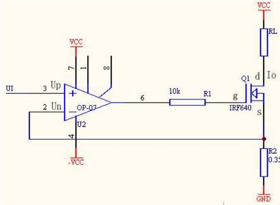
Figure. 4
Adjustment tube in the circuit using high-power field effect tube IRF640. field effect tube, it is easier to realize the voltage linear control of current, not only to meet the requirements of the output current up to 2A, but also better to achieve the voltage approximate linear control of current. Because when the field effect tube works in the saturation region, the leakage current Id approximate voltage Ugs control current. That is, when Ud is a constant, it satisfies: Id = f (Ugs), and as long as Ugs is constant, Id is constant. In this circuit, R2 is the sampling resistor, which is wound with Kang copper wire (resistance value varies less with temperature) and has a resistance value of 0.35 ohm. Operational amplifier OP-07 as a voltage follower, UI = Up = Un, field effect tube Id = Is (gate current is relatively small, negligible) so Io = Is = Un/R2 = UI/R2. Because Io = UI/R2, the circuit input voltage UI to control the current Io, that is, Io does not change with the change of RL, thus realizing the voltage-controlled constant current. At the same time, from the design requirements: since the output voltage varies over a range of U〈=10V,Iomax=2A,it can be concluded that the load resistance RLmax=5 ohms.
Power supply circuit design
This system has high requirements for the power supply. Design of the power supply to ensure both high stability of the power supply, but also to ensure that the power supply can output a current greater than 2A, so the system uses a three-stage tube 1264 to expand the current and the use of the power supply must give full consideration to the efficiency of the power supply. Power supply circuit shown in the figure, this power supply circuit uses the LM317 and LM337, its output voltage is continuously adjustable, the output voltage to +15V and -15V to supply hardware circuits to use, of which -15V power supply for op-amps, do not need to amplify the current; and +15V power supply load current requirements are not Less than 2A, so the use of three-stage 1264 to expand the current. In addition, LM7805 is used to generate +5V voltage for SPCE061A microcontroller.
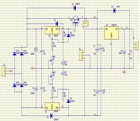
Figure. 5
Linear constant current source, switching constant current source, high reliability, easy to adjust, has been applied in scientific research. Among them, linear constant current source is suitable for constant current discharging of battery, switching constant current source is suitable for constant current charging of battery, and constant current source composed of integrated regulator is suitable for resistance measurement, etc. With SPCE061A MCU as the central controller, this system is characterized by strong function, reliable performance, small size and simple circuit. This system can step 1mA minimum , and the precision is also higher. The output current range is wider. In the hardware part of the sampling resistor thermal stability to be better, the core module in the hardware for the pressure-controlled constant-current source, the core components of the field-effect tube performance and stability are higher than the triode.


