

How to effectively reduce static electricity damage to electronic components?
2024-11-12 10:25:45 1149
In the winter, static electricity on electronic components and equipment damage can not be ignored (although it is now summer), the production line every year to increase the investment in anti-static measures. So, how should we effectively reduce and prevent static electricity damage to electronic components?
In the SMT process, electrostatic discharge will cause damage to electronic components or failure, with the increase in IC integration and components of the gradual shrinkage, the impact of static electricity has become more serious.
According to statistics, the factors that lead to the failure of electronic products, static electricity accounted for 8% to 33%, and the annual loss of electronic products due to static electricity, up to billions of dollars.
Therefore, in the SMT production, the implementation of electrostatic protection measures is very important, this article will be from the generation of static electricity to the protection of components and scenes, etc., details of how to do a good job of electrostatic protection measures.
I. How does static electricity?
Friction: any two objects of different materials in contact with the friction and then separation, you can generate static electricity.
Induction: for conductive materials, as electrons can flow freely on the surface of conductive materials, if it is placed in the electric field, due to charge repulsion, anisotropic suction, positive and negative charge transfer, thereby generating static electricity.
Conduction: the same for conductive materials, because electrons can flow freely on its surface, if in contact with a charged object, the charge transfer occurs, thus generating static electricity.
As shown in the figure below, Figure 1 is a schematic diagram of the human body electrostatic model. Circuit when the switch is connected to A, the voltage source on the capacitor charging, simulating the process of human accumulation of static electricity; when the switch is connected to B, stored in the capacitor on the charge through the resistor (equivalent human body resistance) to the device discharge, equivalent to the human body touching the device instantly, the discharge process will produce a certain size of the instantaneous discharge current in just a few hundred microseconds, which may be the device inside the device is damaged.
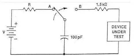
Figure 1: Human static electricity model circuit
II. Why is the instrument so easy to be electrostatic breakdown?
Instrumentation products usually need to meet the IEC61326-1 standard electromagnetic compatibility requirements, the standard contains a static immunity test, the requirements of instrumentation products based on IEC61000-4-2, need to meet the contact discharge 4KV, air discharge 8KV test level.
1. The more high-frequency instruments, electrostatic protection ability is relatively weak
Oscilloscope is a high-resistance equipment, very susceptible to external electrostatic induction and generate static electricity, but the charge is difficult to discharge in the electrostatic strong occasions, it is easy to electrostatic breakdown. Due to the parasitic parameters of the electrostatic protection device will affect the measurement of high-frequency signals, so high-frequency instruments can not be integrated into too many electrostatic protection devices, which leads to a decline in electrostatic protection capabilities. Therefore, the more high-frequency instruments need to pay more attention to electrostatic protection.
2. The wrong use of the operation can also lead to electrostatic damage to the instrument
For oscilloscopes, be sure to pay attention to the first grounded after the signal. For example, the following two operations are very dangerous and must be avoided.
Wrong operation 1: When using an oscilloscope to measure the circuit board, the probe first signal line, probe ground after grounding.
Wrong operation 2: Touch the probe needle directly with your hand, as shown in Figure 2.
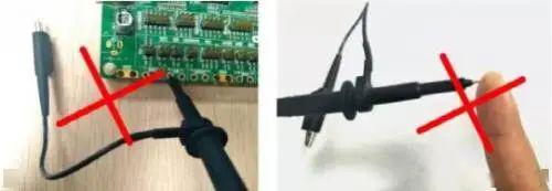
Figure 2: Wrong operation
III. We can do through what measures to do static electricity protection?
Although the instrument has a certain anti-static ability, but if the environmental static electricity than the standard requirements are higher, the instrument may still be damaged by static electricity, so in the use of the instrument some basic electrostatic protection measures are still necessary to understand.
In fact, electrostatic protection mainly follows the principle of “release after operation”:
1. Keep the instrument well grounded
The purpose is to discharge static electricity to earth. If you have no choice but to need to measure the floating ground, be sure to ground before the specific operation to release static electricity.
2. Before the measurement of the environment to do static treatment
If conditions permit, the production line needs to lay anti-static floor, wear anti-static clothing, anti-static shoes and so on. For the use of high-frequency instruments but also by wearing a static hand ring will be on the body of the electrostatic discharge directly to earth, as shown in Figure 3.
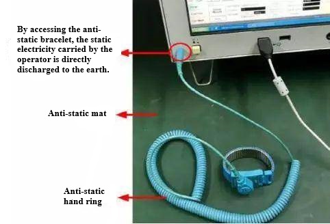
Figure 3: Common anti-static measures for instruments
If the conditions do not allow, we have a more convenient way to contact the instrument before the first hand to touch something well grounded, it is best to operate every once in a while.
3. Be sure to ground first, then connect the signal
The device under test will also have static electricity (contact resistance is small, the release current may be higher), so the use of oscilloscopes to measure the circuit board, you must first connect the probe ground, and then connect the probe to the signal line; if you first connect the probe to the test point, and then connect the probe ground, then the static electricity will be released directly through the oscilloscope signal circuit, it may be possible to penetrate the internal device of the oscilloscope, which is a very important operational step.
In the design of many boards have similar applications, such as the PCIE board shown in Figure 4, the clock signal gold finger to be significantly shorter than the other pins, is to insert the card so that the ground first contact for discharge, the signal line after the contact on the safe.
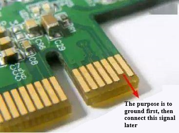
Figure 4: Common anti-static measures for boards
4. Try not to touch the exposed interface
For electronic equipment exposed interface, be sure not to touch with your hands, including oscilloscope probes probe is also so.
IV. The summary
Operators in the use of instruments, must have a sense of electrostatic protection, especially dry winter, so as to minimize the damage of electrostatic discharge on the instrument.


