

Selection and implementation of BLDC control strategy
2024-10-21 11:15:06 662
Understanding the difference between trapezoidal, sinusoidal and field oriented control can help engineers understand the value of field oriented control (FOC) and the options available to optimize their designs.
BLDC motors are smaller, lighter and quieter than traditional brushed DC motors, while also improving reliability and energy efficiency in consumer, industrial, automotive and medical applications. Their brushless construction simplifies equipment design and maintenance by eliminating mechanical wear, conductive dust, audible noise and arcing.
Control strategies range from basic trapezoidal control to smoother sinusoidal control and field oriented control (FOC), allowing engineers to choose from a variety of options to balance complexity and cost with performance and controllability.
Six-step or trapezoidal control
A simple “on/off” excitation method is used to energize three stator windings in sequence, which acts on the static magnetic field of permanent magnets in the rotor, causing it to rotate. The cycle consists of six pulses applied to each winding to perform one rotation. The waveform is relatively easy to generate and produces a trapezoidal counter electromotive force, as shown on the left side of Figure 1. However, the force on the rotor is not exactly along the tangential direction, which is ideal for ensuring continuous maximum torque. The motor rotates with a periodic radial component, which reduces efficiency and leads to wear, heat and so-called “torque fluctuations”.
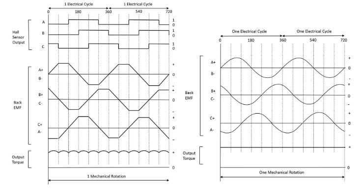
Figure 1. Six-step sinusoidal control of a BLDC.
Sinusoidal and Field Oriented Control
Theoretically, the application of sinusoidal excitation produces a smoothly rotating magnetic field that is always perpendicular to the magnetic field of the rotor magnets, resulting in consistent torque, as shown on the right side of Figure 1. In practice, effects such as winding inductance and reverse electromotive force can cause the resulting current and magnetic field to phase shift, preventing simple sinusoidal control from providing smooth and accurate control.
Field Orientation Control (FOC) dynamically corrects the magnitude and direction of the stator magnetic field to achieve the torque and speed required by the application. The algorithm calculates the optimum winding current based on instantaneously measured rotor position.
Field Orientation Control maximizes torque
In principle, the FOC controls the AC excitation current so that the angle of the magnetic field generated is always perpendicular to the magnetic field of the rotor magnets. This produces maximum torque, eliminates torque fluctuations, improves efficiency, and minimizes mechanical wear by eliminating radial loads on the bearings.
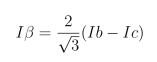
The stator winding currents and the resulting magnetic field strength and direction can be expressed as three rotational vectors that are separated by 120 degrees in a common static frame. To minimize torque fluctuations and maximize efficiency, these currents, I U, I V and I W, must be balanced so that their net sum is zero. FOC aims to achieve this balance by first applying a “Clarke” transformation. This reduces the currents to two rotating vectors of magnitude Iα and Iβ, separated by 90 degrees in the static frame:
Converting these vectors into the static components I D (direct) and I Q (quadrature) in the rotating reference plane, it is possible to relate them to the position of the rotor as it rotates. This is done using the “Park” transformation:
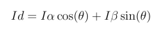
θ is the rotor angle around the static Iα and Iβ coordinate systems.
In steady state, I D and I Q are constant values that can be interpreted as components of the stator winding currents, representing tangential and unwanted radial torque, respectively. the FOC uses these values as inputs to a feedback loop, typically a Proportional Integral (PI) controller, to maximize I Q and minimize I D to zero. The resulting error amplifier outputs, V D and V Q, are Park inverted and Clarke inverted, and subsequently pulse width modulated to drive the power stage, producing three sinusoidal stator winding currents. The programmable gain values Kp and Ki in the PI controller must be optimized for transient response and steady-state accuracy, respectively, and are heavily dependent on the actual motor parameters, particularly winding resistance and inductance. The programmable gain values Kp and Ki must be optimized for transient response and steady-state accuracy, respectively, and are heavily dependent on actual motor parameters, especially winding resistance and inductance. However, advanced FOC controllers, such as those from Qorvo [1], have an auto-tuning feature that “learns” the characteristics of the connected motor. Figure 2 shows the outline of a BLDC motor controller using FOC.
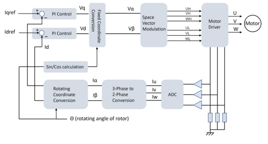
Figure 2. FOC scheme for driving a BLDC motor.
Applications that particularly benefit from FOC are those that need to minimize noise or vibration or require low harmonic contact. In addition, FOC allows the application to run at higher than nominal speeds when needed. This is achieved by “magnetic field weakening”, in which the reaction potential is deliberately reduced by lowering the control current I D to a negative value. This reduces the effective rotor field and allows higher speeds, although torque is reduced.
Sensing rotor position and winding current
The rotor angular position in the FOC must be known to resolve the Id and Iq components. It is also necessary to measure the stator winding current.
There are several ways to sense rotor position. Sensorless monitoring can infer the position from the winding currents, reverse electromotive force, and the motor characteristic model. However, starting at high loads can be difficult and it may be necessary to use a ladder drive to start the motor. In this case, one winding is not energized at any given moment, and the presence of a zero-crossing of the reaction potential provides an accurate indication of position. The application can then change to sinusoidal FOC when the motor is running.
Alternatively, the use of Hall sensors to detect rotor position can be used to start up under high load conditions and enable accurate torque control. More expensive options are to use magnetic resolvers or encoders with quadrature outputs, which provide highly accurate position measurement and can sense the direction of rotation.
In addition, there are many ways to measure the winding current. The most accurate method is to sample all three winding currents simultaneously using three sensing resistors, each connected to an ADC. the usual method is to measure the inverter branch current (Fig. 3, left).
For cost-sensitive applications, a single shunt resistor can be used to efficiently measure the DC link current (Fig. 3, right). Only one ADC is required and phase currents are calculated using the single shunt current reconstruction method. The timing of the current samples is critical to capturing an accurate average value. If the effective vector duration is less than the minimum measurement period, effects such as ringing may affect accuracy. Asymmetric current sampling can overcome this problem but requires more complex calculations.
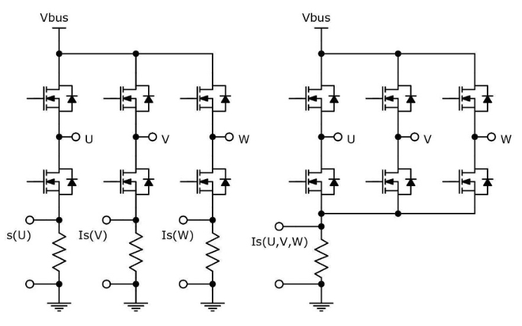
Figure 3. Monitoring BLDC motor currents using the triple shunt (left) and single shunt (right) methods.
Implementing BLDC FOC
A complete motor control application requires power management, analog sensing, PWM generation, gate drive functions, and a processing core responsible for executing the FOC algorithm. System-on-Chip devices optimized for motor control, such as Qorvo's Arm® Cortex®-based PAC5xxx family, integrate this circuitry into a single package. One variant in this family even integrates power MOSFETs to directly drive low-power BLDC motors for applications such as handheld devices and tools. These Power Application Controller® ICs support the methods discussed in this paper, including sensorless rotor position measurement or detection using Hall sensors or quadrature encoders, and single- or triple-shunt current sensing. They also allow hybrid trapezoidal/FOC modes to ensure startup and magnetic field weakening for higher than nominal speed operation.
Conclusion
Understanding the differences between trapezoidal, sinusoidal, and magnetic field oriented control, as well as the basic principles of operation, can help engineers choose the right control strategy when developing BLDC motor applications. Magnetic field directional control provides precise speed control, fast dynamic response, and minimal torque fluctuations, and can now be implemented using a single-chip control IC.


