

What's going on with noise in circuits? How can it be suppressed?
2025-04-27 11:43:00 902
The term noise in electronic circuits can be generalized as a generic term for all signals other than the intended signal.
Initially, the electronic signals that cause the noise emitted by audio equipment such as radios were called noise. However, the consequences of some non-purpose electronic signals on electronic circuits are not always related to sound, and thus the concept of noise has been gradually expanded.
Figure. 1
For example, the electronic signals that cause white streaks on a video screen are also called noise. It is possible to say that all signals in a circuit other than those intended for the circuit, regardless of whether they affect the circuit or not, can be called noise.
For example, ripples or self-excited oscillations in the supply voltage can adversely affect the circuit, causing the audio device to emit an alternating current sound or causing the circuit to operate incorrectly, but sometimes may not lead to these consequences. Such ripples or oscillations should be referred to as a type of noise in the circuit. There is a certain frequency of the radio wave signal, the need to receive this signal to the receiver, it is the normal purpose of the signal, and to another receiver it is a non-purpose signal, that is, noise.
In electronics often use the term interference, sometimes confused with the concept of noise, in fact, there is a difference. Noise is an electronic signal, and interference refers to a certain effect, is due to noise causes an adverse reaction to the circuit. Whereas there is noise in a circuit, there is not necessarily interference. In digital circuits. Often can be observed with an oscilloscope in the normal pulse signal mixed with some small spike pulse is not expected, but a noise. However, due to circuit characteristics, these small spike pulses are not enough to cause the logic of the digital circuit to be affected and disorganized, so it can be assumed that there is no interference.
When a noise voltage is large enough to disrupt a circuit, that noise voltage is called an interference voltage. And the maximum noise voltage added to a circuit or a device, when it can still maintain normal operation, is called the interference tolerance or immunity of the circuit or device. Generally speaking, noise is difficult to eliminate, but you can try to reduce the intensity of the noise or improve the immunity of the circuit so that the noise does not form interference.
How can noise generation in electronic circuits be suppressed?
This stuff is mainly generated due to the digital circuits and power supply part of the circuit. In digital circuits, high-frequency digital levels are prevalent, and these levels can produce two kinds of noise:
1, electromagnetic radiation, like the antenna of the TV, by transmitting electromagnetic waves to interfere with the circuit next to it, that is, you said the noise. 2, coupling noise, refers to the digital circuits and the circuits next to the existence of a certain degree of coupling, the noise can be directly in the electrical appliances to directly affect the other circuits, this noise is more powerful.
Noise present on the power supply: If it is a linear power supply, first of all, the low frequency 50Hz is a serious source of interference. As the primary AC power coming in itself is not pure, and is a wave of sinusoidal wave, easy to produce electromagnetic interference on the circuit next to it, that is, electromagnetic noise. If it is a switching power supply, the noise is more serious, switching power supply work in the high-frequency state, and in the output part of the existence of very dirty harmonic voltage, these circuits can produce a lot of noise on the whole.
Prevention methods: reasonable grounding, the use of differential structure transmission of analog signals, the power supply output in the circuit with decoupling capacitors, the use of electromagnetic shielding technology, analog and digital ground separation, signal lines on both sides of the bottom line, ground isolation and so on. In fact, I said these in the removal of noise is just the tip of the iceberg, even if you play 30 years of electronic people will not fully grasp all of these techniques, because understanding the mastery of this kind of thing requires a very strong technical basis and considerable experience, but I told you that these in general has been enough.
The noise floor is caused by the circuit itself, due to impurity of the power supply, inappropriate phase margins and gain margins of the circuit, etc. The circuit itself and the devices are responsible for this. This part needs to be improved during circuit design.
Other noise is due to the circuit layout and wiring is not reasonable and so on that factors, electromagnetic compatibility, interference between the wires and so on.
The elimination of noise in analog circuits depends more on experience than on scientific evidence. Designers often encountered is the analog hardware part of the circuit design, but found that the circuit noise is too large, and have to re-design and wiring. This “try-and-see” approach can be successful after a few setbacks. However, a better way to avoid noise problems is to follow some basic design guidelines and apply knowledge of noise-related fundamentals when making decisions early in the design process.
Design Methods for Low Noise Preamplifier Circuits
Preamplifiers play a vital role in audio systems. This article first explains how engineers should select components appropriately when designing preamplifiers for home audio systems or PDAs. Subsequently, the sources of noise are exhaustively analyzed to provide guidelines for designing low-noise preamplifiers. Finally, the preamplifier of a PDA microphone is taken as an example, listing the design steps and related considerations.
A preamplifier is a circuit or electronic device placed between a source and an amplifier stage, such as an audio preamplifier placed between a compact disk player and a power amplifier of a high-level audio system. Preamplifiers are designed to receive weak voltage signals from a source, and the received signals are first amplified with a small gain, and sometimes adjusted or corrected even before they are transmitted to the power amplifier stage, such as in the case of audio preamplifiers, where the signals can first be equalized and controlled in pitch. Whether for the home audio system or PDA design preamplifier, we have to face a very headache, that is, what components should be used in order to appropriate?
Component Selection Principles
Many preamplifiers nowadays use operational amplifier ICs because of their compact size and excellent performance. When designing a preamplifier circuit for an audio system, it is important to know how to select the appropriate specifications for the operational amplifier. During the design process, system design engineers often face the following questions.
1. Is it necessary to use a high-precision operational amplifier?
The input signal level amplitude may exceed the error tolerance of the operational amplifier, which is not acceptable to the operational amplifier. If the input signal or common-mode voltage is too weak, the designer should use a high-precision operational amplifier with a very low compensation voltage (Vos) and a very high common mode rejection ratio (CMRR). Whether or not to use high-precision operational amplifiers depends on the system design needs to achieve how many times the amplification gain, the greater the gain, the higher the need to use more accurate operational amplifiers.
2. What kind of power supply voltage is needed for op-amps?
This question depends on the dynamic voltage range of the input signal, the overall power supply voltage of the system and the output requirements can be decided, but different power supply rejection ratio (PSRR) will affect the accuracy of the operational amplifier, which is most affected by the use of battery-powered systems. In addition, the power consumption is also directly related to the internal circuit quiescent current and supply voltage.
3. Does the output voltage need to be full swing?
Low supply voltage designs often require full-swing outputs in order to fully utilize the entire dynamic voltage range to extend the output signal swing. As for the problem of full-swing inputs, the configuration of operational amplifier circuits will have its own solution. Since the preamplifier is generally used in inverting or non-inverting amplifier configurations, the input does not need to be full-swing due to the fact that the common-mode voltage (Vcm) will always be less than the output range or equal to zero (with rare exceptions, such as single-supply-voltage operational amplifiers with a floating ground).
4. Is the gain bandwidth issue more of a concern?
Yes, especially for audio preamplifiers, this is a great concern. Since human hearing can only perceive the sound from about 20Hz to 20kHz frequency range, so some engineers design audio systems will ignore or trivialize this “narrow range” of bandwidth. In fact, important technical parameters that characterize the performance of an audio device, such as low THD, fast slew rate, and low noise, are essential for high-gain bandwidth amplifiers.
In-depth understanding of noise
In the design of low-noise preamplifier before the engineer must carefully examine the noise from the amplifier, in general, the operational amplifier noise mainly from four aspects:
1, thermal noise (Johnson): due to irregular fluctuations in the electronic energy of the current in the electrical conductor with broadband characteristics of the thermal noise generated by the root-mean-square value of the voltage of the positive side of the bandwidth and the electrical conductor resistance and absolute temperature has a direct relationship. For resistors and transistors (such as bipolar and field effect transistors), because its resistance value is not zero, so the impact of this type of noise can not be ignored.
2, flicker noise (low-frequency): due to the surface of the crystal is constantly generated or integrated carriers and noise. In the low-frequency range, this kind of flicker in the form of low-frequency noise, once into the high-frequency range, these noises will become “white noise”. Flicker noise is mostly concentrated in the low-frequency range, the resistor and semiconductor interference, and bipolar chip interference than the field effect transistor.
3, shooting noise (Schottky): Schottky noise by the semiconductor with particle characteristics of the current carriers generated by the root mean square value of the current and the chip has a direct relationship with the average bias current and bandwidth. This noise has broadband characteristics.
4, popcorn noise (popcornfrequency): semiconductor surface if contaminated will produce this noise, the impact of up to a few milliseconds to a few seconds, the reason for the noise is still unknown, under normal circumstances, there is no certain pattern. The use of cleaner processes in the production of semiconductors will help to minimize this type of noise.
In addition, the amount of noise varies greatly from amplifier to amplifier due to differences in transistor construction, as different operational amplifiers use different structures for their input stages. Here are two specific examples.
Bipolar input operational amplifier noise: noise voltage is mainly caused by the thermal noise of the resistor and the high-frequency shooting noise of the input base current, and the low-frequency noise level depends on the low-frequency noise generated by the base current of the input transistor flowing into the resistor; noise current is mainly generated by the shooting noise of the input base current and the low-frequency noise of the resistor.
Noise of CMOS input operational amplifier: the noise voltage is mainly caused by the thermal noise of the channel resistor in the high-frequency region and the low-frequency noise in the low-frequency region, the corner frequency (cornerfrequency) of the CMOS amplifier is higher than that of the bipolar amplifier, and the broadband noise is also much higher than that of the bipolar amplifier; the noise current is mainly generated by the shooting noise of the input gate leakage, and the CMOS amplifier's noise CMOS amplifier noise current is much lower than the bipolar amplifier, but every 10(C) increase in temperature, the noise current will increase by about 40%.
Engineers must have a deep understanding of the noise problem and do a lot of calculations to accurately express this noise as a number. To avoid complicating the issue, only the most critical parameters of the audio specification are used here.
PDA Microphone Preamplifier Circuit
Here we discuss how to design a microphone preamplifier suitable for use in a PDA. As mentioned above, we must understand that the source is the signal fed into the preamplifier. First, we must know the following information: the type of microphone we plan to use
Microphone output signal level
Microphone impedance and the frequency at which the impedance is specified
Gain specification, which may be limited by the gain bandwidth product of the operational amplifier
Input signal frequency range
Noise specification
For example, the technical specifications of a ceramic microphone are as follows: Impedance: 2.2k (operating at 1kHz)
Output signal: 200 (Vpp)
Audio input frequency range: 100Hz to 4kHz
Thermal noise: 2nV/(Hz Preamplifier gain indicator: 500 (non-inverting), up to 5x gain for the first stage and up to 100x gain for the second stage.
We quote Equation 1:
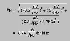
Figure. 2
Equal Input Noise (EIN) = Total Input Reference Noise () x Input Frequency Range
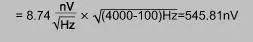
Figure. 3
Output Noise = Equal Input Noise x Gain = 545.81nV x 5 = 2.73uV (for 1-stage gain) or 545.81nV x 100 = 54.58uV (for 2-stage gain).
Total output noise for both amplification stages
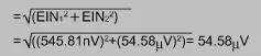
Figure. 4
Signal-to-noise level for 1 volt output = 20 x log(1V ÷ 54.58uV) ≈ 85.3dB
The total output noise of the circuit is approximately the square root of the sum of the average rms values of the rms values of each noise source, and in addition the majority of the output noise usually comes from the source with the largest amount of noise. The actual circuit is shown below.
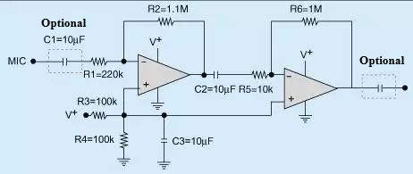
Figure. 5 MIC Preamplifier Circuit Diagram
Please note that this circuit is only suitable for single-supply designs, and the input and output capacitors (C1 and C4) are optional. The applicability depends on how the inputs and outputs of the user's system are connected. If the microphone output is DC-compensated, then an additional C1 input capacitor is required to block the DC signal. An output capacitor can serve the same purpose.
Most of the microphones on the market today are high impedance microphones of about 2k(s) and low impedance microphones of only a few hundred(s), both of which can be designed with the preamplifiers described above. High impedance, high output microphone preamplifiers are simpler and can be configured as non-inverting or inverting amplifiers. Because of its frequency response is relatively flat, so there is no need for special equalization, and the input level is large, the amplifier on the noise requirements are very low, but the high impedance microphone is extremely sensitive to the origin of the noise and magnetic fields. Low-impedance, low-output microphone preamplifiers can also use non-inverting or inverting amplifiers to amplify the input signal, with roughly the same frequency response and equalization requirements as high-impedance, high-output preamplifiers. If the microphone output level is low, engineers must pay attention to the use of low noise operational amplifiers. For example, a better performing low-noise operational amplifier should produce low input reference voltage noise and the noise should not exceed 10nV/((Hz).
Analysis and Measurement of Noise Inherent in Operational Amplifier Circuits
Any undesired signal in an electronic system might be referred to as noise. Both errors in precise measurements and deterioration of the audio signal quality can result from noise. Electronic design engineers at the board and system levels are interested in figuring out how noisy their designs are in the worst-case scenarios, as well as how to minimize noise and use measurement methods to precisely verify the designs' feasibility.
Both intrinsic and extrinsic noise are forms of noise that have an impact on how well electrical circuits function. Digital switching, 60Hz noise, and power switching are common instances of external noise, which originates from external sources. Broadband noise, thermal noise, and flicker noise are the most prevalent types of intrinsic noise, which is produced by the circuit's individual components.


