

Why is grounding resistance generally not greater than 4Ω?
2024-09-14 11:31:06 1233
Grounding resistance is the current from the grounding device into the earth and then flow through the earth to another grounding body or to the distant spread of the resistance encountered, which includes the grounding line and the grounding body itself, the resistance of the grounding body and the earth's resistance between the contact resistance and the resistance of the earth between the two grounding body or the earth grounding body to the infinite distance of the earth's resistance.
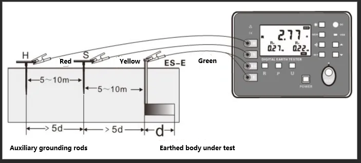
The size of the grounding resistance directly reflects the good degree of contact between the electrical device and the “ground”, but also reflects the size of the grounding network. In the single-point grounding system, strong interference and other conditions, can be used to measure the auxiliary ground pole measurement method.
Grounding is mainly divided into the following four kinds
1, protective grounding: the metal casing of electrical equipment, concrete, poles, etc., due to insulation damage may be electrically charged, in order to prevent this from endangering personal safety and grounding.
2, anti-static grounding: to prevent the effects of electrostatic hazards and will be easy to fuel, natural gas storage tanks and pipelines, electronic equipment and other grounding.
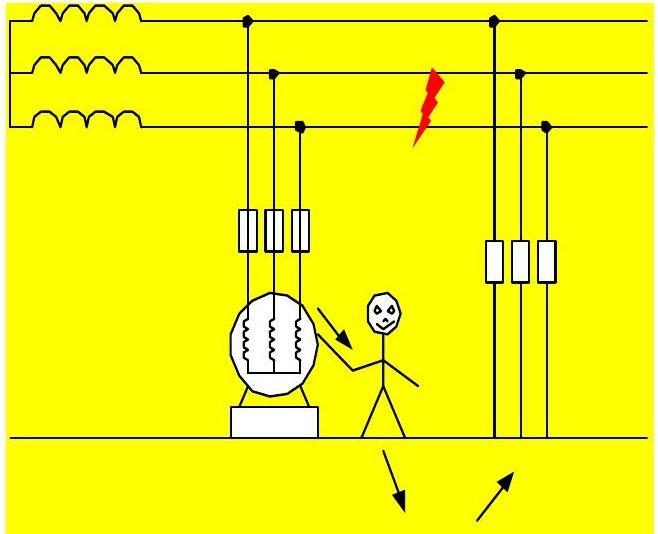
3, lightning grounding: In order to introduce lightning into the ground, lightning protection equipment (lightning rods, etc.) grounding connected to the earth to eliminate lightning overvoltage on electrical equipment, personal property hazards of grounding, also known as overvoltage protection grounding.
4, work grounding: refers to a point of the power system (such as the neutral point) directly to the earth, or by the arc-canceling coil, resistor, etc. and the earth metal connection, such as transformers, transformers, neutral point grounding.
Grounding resistance specification requirements
1, independent lightning protection grounding resistance should be less than or equal to 10 ohms;
2, independent safety protection grounding resistance should be less than or equal to 4 ohms;
3, independent AC work grounding resistance should be less than or equal to 4 ohms;
4, independent DC work grounding resistance should be less than or equal to 4 ohms;
5, anti-static grounding resistance is generally required to be less than or equal to 100 ohms.
6, the common grounding body (joint grounding) should be no greater than the grounding resistance of 1 ohms;
7, the instrument must be carried, used carefully and gently, to avoid violent vibration.
Note: lightning rod ground is a lightning protection ground, if the lightning rod grounding resistance and anti-static grounding resistance are set according to the requirements, then you can anti-static equipment ground and lightning rod ground connected together, because the lightning rod grounding resistance than the electrostatic grounding resistance is 10 times smaller, so most of the lightning accidents will be most of the lightning will be discharged from the lightning rod ground, through the anti-static ground current is negligible.
Why is the grounding resistance generally not greater than 4Ω?
Grounding resistance is the current from the grounding device into the earth and then flow through the earth to another grounding body or to the distant spread of the resistance encountered, the role is to discharge to the earth to ensure safety.
Many household appliances, we tend to touch the shell of the appliance in the process of use, such as refrigerator switch door, washing machine switch door, etc.. But once the appliance malfunctions, the shell will carry a certain voltage, when people touch the shell will be electrocuted, very dangerous, so through the grounding resistor to the earth is very necessary.
For the grounding resistance, we hope that the smaller the better. According to Ohm's law, when the voltage is certain, the resistance is inversely proportional to the current; therefore, when the working voltage is certain, the smaller the grounding resistance is, the more current can pass through it, and the better the current discharge effect. If there is a leakage, all the electricity will be transmitted from the grounded ground wire to the ground.
Why is the maximum limit of grounding resistance 4Ω?
Under normal circumstances, when the electrical system equipment, if a fault occurs, the fault current is not normally greater than 10A, so when the grounding resistance of 4Ω, flow through the grounding resistor generated by the fault voltage can be calculated by Ohm's law: 4x10 = 40 V. And the experimental formation of the standard provides that, in the case of a normal and fault conditions, any two conductors or any conductor between the conductor and the earth shall not exceed the voltage between AC (50 ~ 500Hz) effective voltage. ~500Hz) RMS value of 50V.
This is less than 50V fault voltage is safer, almost impossible to cause human electric shock accident, so the maximum limit of grounding resistance is specified in the 4Ω.
Important reasons
Compliance with laws, regulations and industry standards is an important reason for maintaining the appropriate resistance value of the grounding resistor. Power system construction, operation and management must comply with a series of laws and regulations and industry standards, these norms in the electric power industry, are after countless practice tests to get the lessons learned, especially related to safety provisions, are not the power pioneers through the blood of the lessons learned from practical experience and data, including grounding resistance provisions.
For example, the “Electrical Safety Code”, provides for different types of electrical equipment for the grounding resistance requirements. If the grounding resistance is greater than the specified value, it will lead to the existence of safety hazards in the equipment, which violates the relevant standards and regulations, and more importantly, affects the safety of the surrounding personnel.
Appropriate grounding method
Selection of appropriate grounding method can also ensure that the grounding resistance is not greater than 4 Ω. In different places of electricity, you need to choose the appropriate grounding method. For example, for dry-type transformers, the use of busbar method of grounding can reduce the busbar inductance, improve the anti-interference ability of the equipment, and then keep the grounding resistance is not greater than 4Ω.
Ground environment and the impact of grounding materials
Usually, the soil resistivity of the ground, humidity, temperature and other factors will affect the grounding resistance. Selection of suitable grounding materials and reasonable grounding methods can adjust the size of the grounding resistance to ensure that the grounding resistance is not greater than 4Ω.
Specific applications, grounding is divided into a good variety of scenarios, common grounding include: lightning grounding (that is, the common lightning rod): the smaller the grounding resistance, once struck by lightning when lightning discharged through the grounding wire to the earth the faster, that is, the more secure.
Electrical equipment safety ground (such as washing machine shell grounding):
Many household appliances, especially large appliances like refrigerators, washing machines, air conditioners, etc., need to be grounded for use (chassis grounding). When there is an electrical leakage from the housing, the lower the grounding resistance, the more the leakage will be transmitted to earth through the grounding wire. But if the grounding resistance is too large (if larger than the human body resistance), when a person touches the chassis, the human body becomes the ground wire, the current flows from the human body into the earth, resulting in human electrocution, quite dangerous.
There are also electronic devices within the work of grounding, etc., are the smaller the better grounding resistance. There are some electronic equipment will produce static electricity, if the grounding resistor is connected, it can prevent the danger arising from static electricity.


