

DC Power Supply True RMS Measurements
2024-10-24 10:54:53 962
The ripple and noise of a DC power supply are important parameters for evaluating the quality of the power supply, and they reflect the instability and interference of the power supply output. Large ripple or noise may lead to unstable system operation, increased sensor error, distortion of analog signals, and other problems. Therefore, it is very important to properly measure and evaluate ripple and noise levels when designing and selecting power supplies.
This article will describe how to test DC power supplies for ripple and noise and provide the appropriate measurement methods and techniques. The AC spurious components of a DC power supply output are known as ripple and noise, or Periodic and Random Deviation (PARD ), and are parameters describing the quality of the power supply, measured as True RMS (RMS) or Peak-to-peak (Vpp), and are usually specified in the 20Hz ~ 20MHz bandwidth range, and they reflect the instability and disturbances in the power supply output. However, their specific definitions and characteristics differ slightly.
Power Ripple
Power Ripple is the periodic variation or fluctuation present in the output of a power supply. It is usually present in the form of an AC signal in the output of a DC power supply. Power ripple can be caused by factors such as power supply design, power supply filters, or it can be affected by load variations or other external disturbances. The frequency of power ripple is usually related to the input frequency of the power supply, such as AC power supply ripple frequency of 50Hz or 60Hz.
Power Noise
Power noise refers to the non-periodic random disturbances present in the output of a power supply (see Figure 1.) These disturbing signals can come from the internal electronics of the power supply itself or from external environmental disturbances. Power noise is usually broadband and widely distributed across the frequency spectrum.
The magnitude of power supply ripple and noise is often measured in either peak-to-peak (Vpp) or true effective value (RMS) in volts (V), and it is important whether the power supply ripple and noise values are peak-to-peak or RMS. Peak-to-peak values provide information about high-amplitude, short-duration spikes, while RMS values are useful in determining the expected signal-to-noise ratio.
Both power supply ripple and power supply noise have an impact on circuit performance and system stability. Large ripple or noise may cause problems such as unstable system operation, increased sensor error, and distortion of analog signals. Therefore, when designing and selecting power supplies, it is necessary to consider the power supply ripple and noise levels according to the application requirements and take appropriate measures to minimize their effects, so how to correctly measure the ripple and noise of the power supply becomes critical.
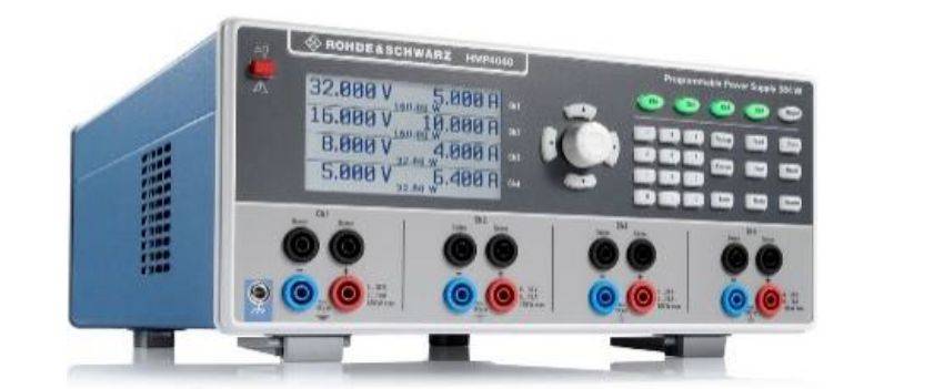
For DC power supplies, the electronic load used should operate in CR mode when testing ripple and noise. The load's ripple and noise indicators should be lower than those of the power supply under test. This is especially important when measuring the ripple and noise of the power supply, because linear power supplies usually have excellent ripple and noise indicators, such as Rohde & Schwarz's HMP series of power supplies with voltage ripple and noise of up to 1.5mV (RMS) or less. An adjustable AC source should also be used to apply input to the power supply under test. Ripple and noise measurements are made at the specified minimum and maximum AC inputs to the power supply and at the specified minimum and maximum source frequencies.
HMP4000 Series Power Supplies (HMP4040) Peak-to-peak (Vpp ) Measurements
Test equipment: AC power supply, electronic load, digital oscilloscope, isolation capacitor
When making ripple and noise measurements, it is important to properly connect the instrument and the power supply under test. Since ripple and noise include low-level broadband signals, the main test setup should pay attention to ground loops, proper shielding, and impedance matching. A digital oscilloscope can be used for peak-to-peak measurements. Since high-frequency noise spikes need to be measured, the oscilloscope's sampling rate should be at least five times higher than the highest ripple and noise frequencies for proper sampling. To eliminate cable ringing and standing waves, typical configurations include coaxial cables terminated at 50 Ω at both ends, with capacitors connected in series with the signal path to block DC currents.
At the same time, the power ripple based on the grid 220V AC input contains switching frequency and industrial frequency components, the industrial frequency component is a 100Hz signal after rectification, it takes 20ms to capture two complete 100Hz cycles, so it is recommended that the time base is set to 2ms/div or more, from the depth of storage = sampling rate × sampling time can be seen, to increase the oscilloscope's storage depth can be indirectly improve the oscilloscope's Sampling rate: When you want to measure the waveform for a longer period of time, because the storage depth is fixed, so you can only reduce the sampling rate to achieve, but this will inevitably cause a decline in the quality of the waveform; if you increase the depth of storage, you can measure at a higher sampling rate to obtain undistorted waveforms, so the depth of storage and the sampling rate of the power supply in the test of the ripple and noise in the test results is very important for the accuracy of the test results, through the use of Rohde By using Rohde & Schwarz's MXO44 series oscilloscopes with 800M memory depth, 5Gsample/s sampling rate and up to 18-bit ADC architecture, the waveforms of power supply ripple and noise can be captured more completely.
True RMS Measurement
Test equipment: AC power supply, electronic load, digital oscilloscope, high-frequency millivoltmeter, isolation capacitor true RMS measurement requires the use of high-frequency millivoltmeter, as with peak-to-peak submeasurements, both measurements should be prevented from ground loops. Since most oscilloscopes and high-frequency millivoltmeters use ground-referenced inputs and test power supplies with ground-referenced outputs, it is likely that ground loops will be generated as shown in Fig. 5. In this case, to avoid ground-loop problems, an instrument with a floating-ground (differential) input can be used.
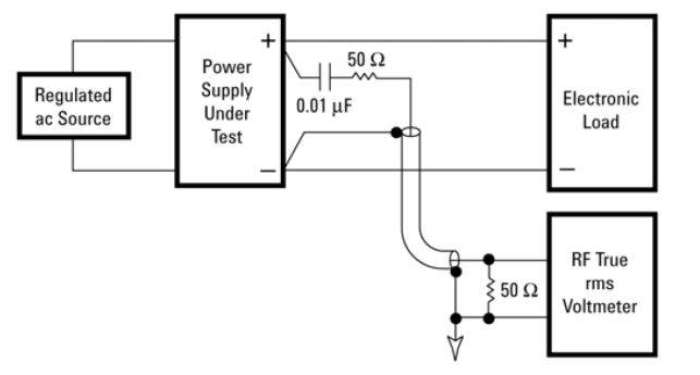
Block Diagram of True RMS Test Connections
For the first set of ripple and noise measurements, the AC source voltage and frequency should be set at the specified minimum values, with the power supply under test at the minimum and then maximum rated load values. For the second set of ripple and noise measurements, the AC source should be set at the specified maximum amplitude and frequency, with the power supply under test at minimum and then at maximum load value. For testing multiple output power supplies, all other outputs should be set at the minimum load, then to the maximum load when making ripple and noise measurements for each output.
Test Precautions:
1, try to use a high vertical resolution oscilloscope (recommended 8bit or more);.
2, the oscilloscope sample rate indicator for the ripple and noise frequency of at least 5 times.
3, choose a long storage depth oscilloscope to ensure that the waveform is not distorted.
4, try to use the oscilloscope minimum range to reduce the oscilloscope noise floor.
5, according to the need to use the bandwidth limit function.


